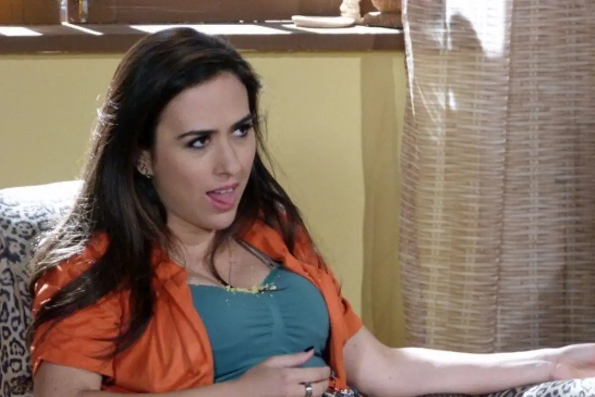
Farm structures ... - Ch4 Structural design: Columns (2023)

Columns

Contents - Previous - Next

The column is essentially a compression member, but the mannerin which it tends to fail and the amount of load which causesfailure depend on:

  • The material of which the column is made.
  • The shape of cross section of the column.
  • The end conditions of the column.

The first point is obvious - a steel column can carry agreater load than timber column of similar size.

Columns having a large cross-section area compared to theheight are likely to fail by crushing. These "shortcolumns" have been dealt with earlier.

Buckling of Slender Columns

If a long, thin, flexible rod is loaded axially incompression, it will deflect a noticeable amount. This phenomenonis called buckling and occurs when the stresses in the rod arestill well below those required to cause a compression/shearing-type failure. Buckling is dangerous in that it is suddenand once started is progressive.

Although the buckling of a column can be compared with thebending of a beam, there is an important difference in that thedesigner can choose the axis about which a beam bends, butnormally the column will take the line of least resistance andbuckle in the direction where the column has the least lateralunsupported dimension.

Since the loads on columns are never perfectly axial and thecolumns are not perfectly straight, there will always be smallbending moments induced in the column when it is compressed.

There may be parts of the cross section area where the sum ofthe compressive stresses caused by the load on the column couldreach values larger than the allowable or even the ultimatestrength of the material.

Therefore the allowable compressive strength d cw is reduced by a factor kl , which depends on the slenderness ratioand the material used.

PbW = kl x d cw x A Where:

Pbw = allowable load with respect to buckling

kl = reduction factor, whichdepends on the slenderness ratio

d cw = allowablecompressive stress

A = cross-section area of the column

When the load on a column is not axial but eccentric, abending stress is induced in the column as well as a directcompressive stress. This bending stress will have to beconsidered when designing the column with respect to buckling.

Slenderness Ratio

As stated earlier, the relationship between the length of thecolumn, its lateral dimensions and the end fixity conditions willstrongly affect the resistance of the column to buckling. Anexpression called slenderness ratio has been developed todescribe this relationship:

A = KL / r = l / r where:

A = slenderness ratio

K = effective length factor, whose value depends on how theends of the column are fixed

L = length of the column

r = radius of gyration (r = I / A)

I = effective length of the column (K x L)

There are four types of end conditions for a column or strut:

1 Total freedom of rotation and side movement - like the topof a flagpole. This is the weakest end condition.

The consideration of the two end conditions together resultsin the following theoretical values for the effective lengthfactor. (Kp = factor usually used in practice).

Types of end conditions

Columns and struts with both ends fixed in position andeffectively restrained in direction would theoretically have aneffective length of half the actual length. However, in practicethis type of end condition is almost never perfect and thereforesomewhat higher values for K are used and can be found inbuilding codes. In fact, in order to avoid unpleasant surprises,the ends are often considered pinned (Kp = 1.0) evenif the ends in reality are restrained or partially restrained indirection.

Types of end conditions II

The effective length can be different with respect to thedifferent cross-sectional axes:

1. A timber strut which is restrained at the centre has onlyhalf. The effective length when buckling about the y-y axis, aswhen buckling about the x-x axis. Such a strut can therefore havea thickness less than its width.

2. In the structural framework, the braces will reduce theeffective length to 1 when the column A-B is buckling sideways,but since there is no bracing restricting buckling forwards andbackwards, the effective length for buckling in these directionsis 31. Similarly, the bracing struts have effective lengths ofl/2 d and d respectively.

3. The leg of a frame, which is pinned to the foundation hasthe effective length 1 = 2 L, but if the top is effectivelysecured for sideways movement, the effective length is reduced to1 = L.

4. In a system of post and lintel where the bottom of the postis effectively held in position and secured in direction by beingcast in concrete, the effective length / = 2 L.

Axially Loaded Timber Columns

Timber columns are designed with the following formulae:

A =KL / r and Pbw = kl xd cw x A

Note that in some building codes a value of slenderness ratioin the case of sawn timber is taken as the ratio between theeffective length and the least lateral width of the column l / b

Example 18

Design a timber column which is 3 metres long, supported asshown in the figure and loaded with a compressive load of 15kN.Allowable compressive stress (d cw)for the timber is 5.2N/mm²

Table 4.5 Reduction Factor, (k),for Stresses with Respect to the Slenderness Ratio for WoodColumns

Slend-erness Ratio l / b 2.9 5.8 8.7 11.5 14.4 17.3 20.2 23.0 26.0 28.8 34.6 40.6 46.2 52.0
l / r 10 20 30 40 50 60 70 80 90 100 120 140 160 180
kl 1.0 1.00 0.91 0.81 0.72 0.63 0.53 0.44 0.35 0.28 0.20 0.14 0.11 0.40

b = least dimension of cross section, r = radius of gyration

1 In this case the end conditions for buckling about the x-xaxis are not the same as about the y-y axis. Therefore bothdirections must be designed for buckling. (Where the endconditions are the same, it is sufficient to check for bucklingin the direction which has the least radius of gyration).

Find the effective length for buckling about both axis.Buckling about the x-x axis, both ends pinned:

lx = 1.0 x 3000 = 3000mm

Buckling about the y-y axis, both ends fixed:

Iy = 0.65 x 3000 = 1950mm

2 Choose a trial cross section, which should have its largestlateral dimension resisting the buckling about the axis with thelargest effective length. Try 50 x 125mm. The section propertiesare:

A = b x d = 50 x 125 = 6250mm²

Farm structures ... - Ch4 Structural design: Columns (3)

Farm structures ... - Ch4 Structural design: Columns (4)

3 Find the allowable load with regard to buckling on thecolumn for buckling in both directions.

l x = lx / rx= 3000 / 36.1 = 83 :. kl x= 0.41 (from table 4.5)

l y = ly / ry= 1950 / 14.4 = 135 :. kl x= 0.16 (from table 4.5)

Pw=kl x s c x A

Pwx = 0.41 x 5.2 x 6250mm² = 13325N

Pwy = 0.16 x 5.2 x 6250mm² = 5200N

4 The allowable load with respect to buckling is smaller thanthe actual load. Therefore a bigger cross section has to bechosen. Try 75 x 125 mm and repeat steps 2 and 3.

Section properties:

A = 75 x 125 = 9375mm²

Farm structures ... - Ch4 Structural design: Columns (5)

Farm structures ... - Ch4 Structural design: Columns (6)

Find the allowable buckling load for the new cross section:

l x =lx/rx=3000/36.1 = 83 gives kl x= 0.41

l y =ly/ry=1950 / 21.7 = 90 gives kl y= 0.35

Pwx = 0.41 x 5.2 x 9375 = 19988N say 20kN

Pwy = 0.35 x 5.2 x 9375 = 17063N say 17kN

The allowable load with respect to buckling on the column withcross section 75 x 125mm is therefore 17kN. This is bigger thanthe actual load, but further iterations to find exactly thesection to carry the 15kN are not necessary.

The compressive stress in the chosen cross section will be:

s c = F / A = 9375 =1.6N/mm²

This is much less than the allowable compressive stress whichmade no allowance for slenderness.

Axially Loaded Steel Columns

The allowable loads for steel columns with respect to bucklingcan be calculated in the same manner as for timber. However, therelation between the slenderness ratio and the reduction factor(k') is slightly different as seen in Table 4.6.

Table 4.6 Reduction factor (kl ) forStresses with Respect to the Slenderness Ratio for Steel Columns

l 10 20 30 40 50 60 70 80 90 100 110 120 130 140
kl 0.97 0.95 0.92 0.90 0.86 0.81 0.74 0.67 0.59 0.51 0.45 0.39 0.34 0.30
l 150 160 170 180 190 200 210 220 230 240 250 300 350
kl 0.26 0.23 0.21 0.19 0.17 0.15 0.14 0.13 0.12 0.11 0.10 0.07 0.05

Example 19

Calculate the safe load on a hollow square steel stanchion,whose external dimensions are 120 x 120mm. The walls of thecolumn are 6mm thick and the allowable compressive stress ace =150N/mm². The column is 4 metres high and both ends are heldeffectively in position, but one is also restrained in direction.

The effective length of the column l = 0.85L = 0.85 x 4000 =3400mm.

Farm structures ... - Ch4 Structural design: Columns (7)

l =l / r =3400 / 46.6 = 73 gives Kl = 0.72

Pw = kl x s cw x A = 0.72 x 150 (1202- 1082) = 295kN.

Axially Loaded Concrete Columns

Most building codes permit the use of plain concrete only inshort columns, i.e., columns where the ratio of the effectivelength to least lateral dimension does not exceed 15, i.e. l/r C15. If the slenderness ratio is between 10 and 15, the allowablecompressive strength must be reduced. The tables of figuresrelating to l/ b in place of a true slenderness ratio are onlyapproximate, since radii of gyration depend on both b and dvalues in the cross section, and must be used with caution. Inthe case of a circular column:

b = D / 4 x (12)1/2 0.87D, where

D = the diameter of the column.

Table 4.7 Permissible CompressiveStress (Pcc )in concrete for Columns (N/mm²)

Concrete Mix Slenderness ratio, 1/b
£ 10 11 12 13 14 15
Prescribed
C10 3.2 3.1 3.0 2.9 2.8 2.7
C15 3.9 3.8 3.7 3.6 3.5 3.4
C20 4.8 4.6 4.5 4.3 4.2 4.1
Nominal
1:3:5 3.1 30 2.9 2.8 2.7 2.6
1:2:4 3.8 3.7 3.6 3.5 3.4 3.3
1:1.5:3 4.7 4.5 4.4 4.2 4.1 40

Higher values of stress may be permitted, depending on levelsof supervision of work.

Example 20

A concrete column, with an effective length of 4 metres has across section of 300 x 400mm. Calculate the allowable axial load,if a nominal concrete mix 1:2:4 is to be used.

Slenderness ratio l/b = 400 / 300 = 13.3

Hence table gives Pcc = 3.47 N/mm² byinterpolation.

Pw = Pcc x A = 3.47 x 300 x 400 = 416.4kN.

Eccentrically Loaded Timber and Steel Columns

Where a column is eccentrically loaded, two load effects haveto be considered:

The axial compressive stress caused by the load. The bendingstresses caused by the eccentricity of the load.

Obviously, by the law of superposition, the added stresses ofthe two load affects must be below the allowable stress.

Therefore s /Pcw + f / fw£ 1 i.e.

(axial comp. stress) / (allowable comp. stress) + (bendingstress) / (allowable bending stress) £1

s c / (kl x s cw)+ f / fw £1 which can be transferred to

P1 / (Kl x A) + (s cw / fw) x M / Z £ s cw

Example 2.1 Determine within 25mm the required diameter of atimber post loaded as shown in the figure. The bottom of the postis fixed in both position and direction by being cast in aconcrete foundation. Allowable stresses for the timber used are s cw = 9 N/mm² and fw= 10N/mm².

The load of 5kN on the cantilever causes a bending moment of M= F x e = 5kN x 0.5m = 2.5kNm in the post below the cantilever.

The effective length of the post = L x K = 3000 x 2.1 =6300mm. Try with a post having the diameter 200mm.

The cross sectional properties are:

A = (p D2) / 4 = (p x 2002) / 4 = 31400mm²

A = (p D3) / 32 = (p x 2003) / 32 = 785400mm²

r = D / 4 = 200 / 4 = 50mm

The slenderness ratio =l / r= 6300 / 50 = 126

interpolation in Table 4.5 gives kl= 0.18

P / (Kl x A) + (scw / fw) x M / Z £s cw

30000 / (0.18 x 31400) +(9 / 10) x 2.5 x 106 /167480 = 8.17N/mm2 £9N/mm2

If the post has a diameter of 200mm, it will be able to carrythe loads, but the task was to determine the diameter within25mm. Therefore a diameter of 175mm must also be tried.

l = 43 75 = 144 kl = 0.13

30000 / (0.18 x 24050) +(9 / 10) x 2.5 x 106 /167480 = 23 N/mm2 £9N/mm2

This diameter is too small, so a diameter of 200mm should bechosen. It will be appreciated that the choice of effectivelength based on end fixity has a great effect on the solution.

Plain and Centrally Reinforced Concrete Walls

Basically walls are designed in the same manner as columns,but there are a few differences. A wall is distinguished from acolumn by having a length which is more than five times thethickness.

Plain concrete walls should have a minimum thickness of 100mm.

Where the load on the wall is eccentric, the wall must havecentrally placed reinforcement of at least 0.2% of the crosssection area if the eccentricity ratio e/ b exceeds 0.20. Thisreinforcement may not be included in the load carrying capacityof the wall.

Many agricultural buildings have walls built of blocks orbricks. The same design approach as that shown for plain concretewith axial loading can be used. The maximum allowable compressivestresses must be ascertained, but the reduction ratios can beused as before.

Example 22 Determine the maximum allowable load per metre of a120mm thick wall, with an effective height of 2.8 metres and madefrom concrete grade C 15, a) when the load is central, b) whenthe load is eccentric by 20mm.

Slenderness ratio l / b = 2800 /120 = 23.3

  • a Interpolation gives:

Pcw = 2.8 - 3.3/5 (2.8 - 2.0) = 2.27N/mm² =2.27MN/m²

Allowable load Pw = A x Pcw = 1.0 x 0.12x (1.06 x 106) / 1000 = 272.4kN/m wall

  • b Ratio of eccentricity e / b = 20 / 120 = 0.167

A double interpolation gives:

Pcw = 1 .06N/mm² = 1 .06MN/ m²

Allowable load Pw= 1.0 x 0.12 x (1.06 x 106)/ 1000 = 127.2kN/m wall

Central reinforcement is not required since e / b < 0.20

Table 4.8 Allowable CompressiveStress, Pcw for Concrete Used in Walls (N/mm²)

Concrete Grade or Mix Slenderness Ratio l/b Ratio of Eccentricity of the load e/ b
Plain Concrete Walls Centrally Reinforced Concrete Walls
0.00 0.10 0.20 0.30 0.40 0.50
C20 25 2.4 1.7 0.9 - - -
20 3.3 2.3 1.4 0.8 0.4 0.3
15 4.1 3.0 2.0 0.8 0.4 0.3
£ 10 4.8 3.7 2.7 0.8 0.4 0.3
C15 25 2.0 1.3 0.7 - - -
20 2.8 1.9 1.1 0.7 0.35 0.25
15 3.4 2.4 1.7 0.7 0.35 0.25
£ 10 3.9 3.0 2.2 0.7 0.35 0.25
C10 20 2.3 1.6 1.0 0.5 0.3 0.2
15 2.7 2.0 1.4 0.5 0.3 0.2
£ 10 3.2 2.5 1.8 0.5 0.3 0.2
1:1:3

1:1:2

25 2.3 1.6 0.8 - - -
20 3.2 2.2 1.3 0.8 0.4 0.3
15 4.1 2.9 1.9 0.8 0.4 0.3
£ 10 4.7 3.6 2.6 0.8 0.4 0.3
1:2:3 20 3.0 2.1 1.3 0.7 0.35 0.25
15 3.7 2.7 1.9 0.7 0.35 0.25
£ 10 4.3 3.4 2.5 0.7 0.35 0.25
1:2:4 20 2.7 1.8 1.0 0.6 0.3 0.2
15 3.3 2.3 1.6 0.6 0.3 0.2
£ 10 3.8 2.9 2.1 0.6 0.3 0.2

Higher values of stress may be permitted, depending on levelsof supervision work.

Contents - Previous - Next

References

Top Articles
Latest Posts
Article information

Author: Kimberely Baumbach CPA

Last Updated: 12/10/2023

Views: 5486

Rating: 4 / 5 (41 voted)

Reviews: 88% of readers found this page helpful

Author information

Name: Kimberely Baumbach CPA

Birthday: 1996-01-14

Address: 8381 Boyce Course, Imeldachester, ND 74681

Phone: +3571286597580

Job: Product Banking Analyst

Hobby: Cosplaying, Inline skating, Amateur radio, Baton twirling, Mountaineering, Flying, Archery

Introduction: My name is Kimberely Baumbach CPA, I am a gorgeous, bright, charming, encouraging, zealous, lively, good person who loves writing and wants to share my knowledge and understanding with you.